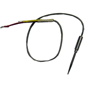
Here are the top 10 tips on installation of a Turbine Inlet Temperature (TIT) probe in your aircraft:
1. Before you even open the package containing the TIT probe, you need to do a little planning i.e. determine the exact location of hole for placing the TIT probe and while doing so, ensure that there is nothing nearby that would interfere with the probe, clamp, clamp screw or wire of the TIT probe.
2. Provide service loops at the instrument – you don’t want to run out of wire during maintenance at some future date.
3. Provide service loops at the engine end as well so that the probe can be swapped to adjacent cylinder positions for troubleshooting purposes.
4. Ensure all wires are kept away from any high temperature components such as exhaust stacks.
5. Ideally, do not splice thermocouple wire using copper wire. We also do not recommend soldering the thermocouple wire. But if you have no other option, solder using zinc chloride flux such as Nokorode brand – not rosin flux.
6. When making the connection, double check the polarity of your Probes & Sensors wire.
7. The standard TIT probe PN M111-T for Experimental Aircraft Engine Monitors comes equipped with a #48 clamp that is placed in the exhaust stack accumulator to a maximum depth of 1/2 inch and approximately 4 inches from the turbine inlet if possible, on the wastegate side of the turbine.
8. Here is a list of things required for installation of the TIT Probes:
I. Slim Line Display (if you haven’t fitted one already), 2 mount. Screws: 1
II. Thermocouple Wire 8’
III. Molex 0.256” Connector Pins: 2
IV. Connector housing: 1
V. Stainless Steel Clamp Thimble: 1
VI. Stainless Steel Exhaust Seal Washer: 1
VII. Stainless Steel Screw Clamp #48: 1
VIII. M-111 Thermocouple Probe: 1
9. If the has been fitted properly than the reading on your panel should be 1650 Fahrenheit.
10. TIT Probe installation schematic:
More information here: https://www.jpinstruments.com/shop/tit-probe/


