This document assumes your general familiarity and knowledge of aircraft engines and its systems. If you are not familiar with it, please seek the services of an authorised aircraft maintenance engineer.
Installation of the JPI manufactured Fuel Scan 450 in cockpit panel:
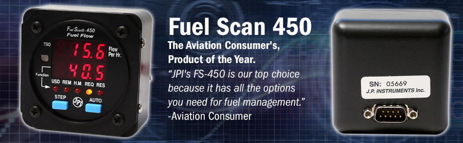
Locate / create a 2.25 or 3.125 diameter hole in the instrument panel, where you would like to mount the indicator. The instrument configures itself automatically for 14 or 28 volt aircraft systems. The depth required for the instrument is 1.5 inches (less connectors) and is 2.6 or 3.5 square behind the panel.
Wiring from sensors to the cockpit:
The fuel flow wires from the probes of the Fuel Scan 450 must be routed through the firewall using flame retarding silicone and fireproof rubber grommets. Using existing hole will make your task much easier. Ensure the wires are routed away from any high temperature areas (i.e. turbochargers, exhaust stacks etc.).
Secure the Fuel Scan 450 probe leads to a convenient location on the engine, allowing for sufficient slack to absorb engine torque. Please ensure the fuel flow transducer wires do not touch any metal parts of the air-frame or engine since abrasion during flight will destroy this wire. Refer to the manual for the wire connection.
Mounting the Fuel Flow Transducer of the Fuel Scan 450 Twin:
Before you start, know that if your aircraft engine is equipped with a fuel return line from the carburettor back to the fuel tank, then you have to use two transducers. The transducer output port should be mounted at same height or ideally, lower than the carburettor inlet port (or fuel servo on a fuel injected engine). In some aircraft, due to space constraints, this might not be possible in which case, please use a loop placed in the fuel line between the Fuel Flow Transducer and the carburettor or fuel. As far as possible, do not hard mount the transducer to the carburettor or fuel servo.
Also, do not remove the caps on the flow transducer until the fuel hoses are ready to be installed. Carefully note the Fuel Flow Indicators direction marked on the transducer – it is important that the fuel must flow in that direction only.
As you fit the flow transducer for the Fuel Scan 450, mount it so the wires exiting the transducer are pointing upwards.
Examine the fuel hose pipes and remove any loose material or dirt that might be deposited. Next, connect the fuel hose pipes. If using air pressure to clean the hose, ensure it does not enter the Fuel Flow Transducer.
More information on Fuel Scan 450 can be obtained here: https://www.jpinstruments.com/shop/fuel-scan-450/
